| |
|

 CARACTÉRISTIQUES CARACTÉRISTIQUES |
| |
Type
: planeur puis planeur motorisé |
Atelier
de fabrication : -- |
|
| |
Envergure : -- ,-- m |
Vitesse minimale
: --- km/h |
|
| |
Longueur : -,-- m |
Vitesse maximale
: --- km/h |
|
| Hauteur : -,--
m |
Taux de chute mini : -- m/s à --
km/h |
| |
Allongement : --,-- |
Finesse max : -- à -- km/h |
|
| | Surface alaire : -- m² | Profil d'aile : ? |
|
| |
Charge alaire : -,- kg/m² |
Nombre de sièges
: 1 |
|
| |
Masse à vide : --
kg |
Nombre de
machines construites : ? |
|
| |
Masse maximale : --- kg |
Années de
fabrication : ---- - ---- |
|
| |
Ballast : non |
Techniques de
construction : Bois et toile |
|
Pas de spécifications connues, relatives à ce planeur.
|
| TRYPTIQUE
ET PLANS |
| |

Extrait
du brevet, un dessin en vue de côté d'une machine proposée par F.
Budig. [3]
|
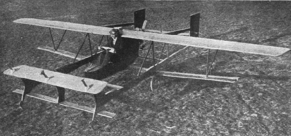
Les photos et le croquis ci-contre
permettent de se faire une idée assez précise de la formule
aérodynamique de cette machine. C'est un sesquiplan : en effet,
l'aile inférieure est de plus faibles envergure et corde que
l'aile principale.Le plan canard stabilisateur à l'avant, en deux
parties : la partie principale servant à la stabilisation longitudinale
automatique, et derrière cette dernière, un volet classique de commande
de profondeur, actionné par le pilote.
Sur les deux versions, il y a également un
plan horizontal à l'arrière, de très petite surface, qui semble être
fixe (?).
On note que le dessin ci-contre prévoit une hélice
tractrice, alors que la machine qu'il a construit ensuite est à hélice
propulsive.
|
| HISTOIRE |
Parmi les machines inscrites au concours de la
Rhön, en Allemagne, en 1921, figurait un curieux planeur de type
canard, dessiné et construit par Friedrich W. Budig.
Le plus
étonnant dans cette machine n'était pas sa géométrie, mais la mise en
oeuvre d'un dispositif de contrôle automatique de la stabilité en
tangage de l'appareil,
particulièrement original. Les photos ci-dessous
attestent des essais effectués, mais les performances en vol ne
semblent pas avoir été convaincantes,
car les comptes-rendus de ne font
guère état de cet appareil. |
|
Les réactions du planeur dans le vent sont
d'abord testées sans pilote
| Les résultats ont dû
être positifs puisque qu'ensuite F. Budig fit d'autres essais
de
sa machine, la pilotant lui-même - [2] |
Puis presque deux
ans plus tard, au début de l'année 1923, la revue anglaise Flight International publie un
article qui reparle de la machine de F. Budig, dans une nouvelle
version, avec un fuselage profondément modifié dans sa partie arrière,
afin de pouvoir y installer un moteur. Il s'agissait d'un moteur de
moto flat-twin BMW développant une puissance de 4 CV. [1]
|  Version
motorisée du Budig [1] Version
motorisée du Budig [1] |
Peu
d'informations ont été données sur les performances obtenues avec ce
planeur motorisé, et il semble manifeste que la puissance développée
par le moteur n'était pas suffisante pour permettre un décollage
de la machine sans assistance, nécessitant un départ traditionnel à la
catapulte. Une fois en l'air la machine devait être capable de voler à
l'horizontale, ou au mieux de s'élever avec un faible taux de montée.
L'hélice étant montée en prise directe sur l'axe moteur, son rendement
était certainement très faible.
Comme de plus la
géométrie de la machine induit une traînée importante, il ne fait
pas de doute qu'il ne devait pas y avoir beaucoup de surplus de
puissance pour permettre une montée. En fait la motorisation
devait seulement permettre de prolonger quelque peu le vol.
|
Un moteur ayant équipé la machine de Budig est actuellement exposé au Deutsches Museum Flugwerft Schleissheim. Budig aurait donc assez rapidement remplacé le BMW initial par ce Salmson A.D. 3. Ce moteur, fabriqué par la Société de Moteurs Salmson, Billancourt, France. Ce moteur d'un peu moins de 1000 cc de cylindrée, développe une puissance de 12 CV (18 kW) à 1800 tours/minute. Il pèse 34 kilogrammes.
Ce moteur a fait ses preuves dans les années 1920 en gagnant le Grand Prix de la Moto-Aviette et le Prix Solex (en 1925). |

Salmson A.D. 3 au Deutsches Museum Flugwerft Schleissheim [photo ClaudeL]
|
| Fin 1922, Le Miroir des Sport dans un court article présentant la machine de BUDIG, titrait : |

Friedrich BUDIG aux commandes de son motoplaneur (en 1922) |

Budig en vol |
 Le
moteur et la curieuse hélice montée en direct sur l'arbre moteur. On
peut avoir de sérieux doutes quant au rendement d'une telle hélice. [1]
|
En mai 1924
se tint le deuxième concours de vol sans moteur de Rossiten, près
de Koenigsberg (Prusse
occidentale). Ce concours a fait date
dans l'histoire du vol à voile car il vit le record du monde de durée
porté à 8
heures 42 minutes 9 secondes par Ferdinand Schultz avec son FS-3
Besenstiel (le 11 mai 1924). Hentzen et Budig participaient à ce
concours et tous deux annoncèrent qu'ils avaient l'intention de se
procurer un moteur Blackburne pour
équiper leurs planeurs respectifs.
Et il semble que les machine
de Budig ne firent plus parler d'elles...
Quoi
qu'il en soit, le Budig peut très probablement être considéré comme
l'un des tout premiers planeurs motorisés, avec le Max de
Hentzen (Wampyr motorisé) qui lui est contemporain.
|
| DESCRIPTION DU SYSTÈME AUTOMATIQUE |
Qu'en
était-il du système de stabilisation longitudinale automatique de Budig
? On ne peut pas espérer trouver description plus précise que celle du
brevet lui-même déposé par Budig en 1921. [3]
Son texte est volontairement
donné ici sans traduction, afin d'apprécier le style propre aux
rédactions de brevet !
" F.W. BUDIG
Flying machine
Application
filed June 16, 1921
1,419,447
Patented June 13, 1922
To all whom it may
concern :
Be it known that I, FRIEDRICH WILHELM BUDIG, citizen of
the state of Prussia, residing at Falkenberg-Grunau, near Berlin, in
the state of Prussia, Germany, have invented certain
new and
useful Improvements in Flying Machines (for which I have filed
applications in France, Aug. 1, 1914, and in Germany Jan. 29, 1920 and
Nov. 20, 1920), of which the following
is a specification.
This
invention relates to a steadying device. It consists in the combination
of the supporting planes proper with an automatically adjustable
steadying plane. This latter plane is
rotatably supported upon an
axle supported in its turn by the flying machine, and its forms,
together with an immovable surface with which it is connected,
preferably by bellows,
a hollow space within which a depression
may be produced in known manner by the mediation of a feeler
surface. The steadying plane is adjusted to various inclinations
by that depression, contrary to the action of a spring. Besides
these arrangements, other ones also forming parts of the present
invention relate to means for correctly adjusting
the steadying
plane, as is particularly necessary for soaring flying apparatus.
|
| Reffering to the
accompanying drawing, Figure 1 is a vertical section
through
a motorless flying machine provided with the novel device
in
question, this latter
being shown in the position it occupies
at too
slow flight ; Figure 2 is a side-view
of the machine, only some
upper
parts (2, 5, 14) and a lower part (9) being shown
in section, and
the
position of the automatic steadying being that which
it occupies
at
normal speed ; Figure 3 is a diagrammatical illustration of the
succession of the swing motions of the machine if flying in
soaring
manner ;
and Figure 4 is a side-view of a soaring flying machine
having
a small auxiliary motor.
The upper body 2 of the steadying
plane is
hinged to a horizontal axle 1 firmly
supported by the frame of the
flying machine. Affixed to said body 2 is
a counterpoise 3,
the
arrangement being such that the total centre of gravity
of the
poise
and the body 2 is located above the common axis of rotation
so
that in
the case of changes of the speed of the flying machine the law of
inertia
initiates a favourable swinging or turn of the upper body
2. | Parallel
with the body 2, and having the same breath as this body, is
an immovable plate 4, to the rear edge of which is hinged the
horizontal rudder 5 for altitude steering.
The body 2 and the
plate 4
are connected with each other by bellows 6 forming or enclosing a
chamber 7 which communicates by a channel or passage 8 with the hollow
feeler
plane 9 which has the shape of an inverted supporting plane and
is provided with a slot 10 extending over the whole of its breadth. 11
is a spring which tends to turn
the body upwards about the
axle 1, that
is to say, to expand the bellows. The position of the parts 2 and 6, if
no partial vacuum within the bellows counteracts the spring,
is
that
shown in Figure 1.
The bellows communicates with the atmosphere not
only through the channel 8, but also through an aperture 12 which is at
the front of the machine and constantly open.
The sectional area
of the
aperture 12 is smaller than that of the slot 10. The supply of the air
through the aperture 12 does not materially affect the degree of
rarefaction
in the bellows as long as the air
entering
through that
aperture flows off through said slot, as in the case during flying with
normal speed. But if the speed decreases, the body 2 can rise,
under
the pressure of the spring 11, far more quickly
than would be
the case
if no supply of air through the aperture 12 would take place, because,
as is known by experience, air, even at reduced speed,
can enter
only
with great difficulty through the slot 10 into the bellows. | In order to accelerate the swinging movement of the
body 2 in the
direction to the plate 4
at an increase of the speed of flight, the
space 7 is connected by one or more air-channels
13 provided in
rigid
parts of the structure preferably tubes, and forming a kind of girder
with the spaces of hollow bodies 14 united with the main supporting
planes.
The tubes 13, or their equivalents, carry the above
described
combination and arrangement
of parts and serve also for
fastening the
means provides for the landing.
The hollow body 14 forms a rigid
piece
for and of the supporting plane and its front portion
the
blowing-at
edge of said plane. The supporting wall of that body 14
differs from an
ordinary hollow supporting plane chiefly by a slot 15 which is
provided
in the lower surface
of the projecting front part of the body 14,
similarly to the slot 10, and the length of
which is about one
fourth
of the length of the slot 10, provided, that the machine
has an
aperture such as 12.
By measurements it is known that at that place
of the supporting frame profile where
the slot 15 is
located a strong depression is produced at quick flight.
This
observation confirms that at slow flightthe slot 15assists the action
of the aperture 12,
and at quick flight assists the action of the
slot 10. |  | Thus, if the angle of incidence at which the
flight takes place is
reduced, then, by the addition of the slot length 15 with the slot
length10, a certain definite amount of air
to be sucked out of the
bellows space 7 is exhausted
more quickly and the body 2 moves
correspondingly quicker in the direction of the plate4 ;
that
could not
be the case without the slot 15.The
manner in which the body 2 is
turned in the one or the other direction will become clear from a
description dealing with flying
in soaring manner, as follows :
Supposing
the machine be soaring motionless in a constant head-wind under a large
angle of incidence. In this case the lifting power R acts at the main
supporting plane,
and the lifting power X acts at the steadying
surface. The lifting power of the horizontal rudder 5 which latter is
controlled by the hand of the pilot, and the buoyancy
of the
stationary
plate 4 may be neglected in these
considerations because said two
influences approximately compensate the downwardly directed power of
the receptacle 9.
Besides the lifting power X, also the power of the
spring 11 acts upon the body 2, in the same direction as said power X,
and, furthermore, also the suction power Z
which is produced in
the
space 7 by the depression and acts
in the opposite direction. These
three powers balance each other at normal flight and determine the
profile
of the steadying surface, as illustrated in
Figure 2.
Now,
if the wind relatively to the flying machine, suddenly grows stronger
owing to a squall or gust, then also the powers X and R increase at the
same time.
Although also the suction power at the slot 10 becomes
greater at the same time, still, the power Z does not immediately vary
because the amount of air to be led away
is increased by the
supply of
air taking place through the aperture 12 and 15.
Besides, the
increased suction power at the slot 12 which tends to increase the
power Z is opposed by three other powers. Firstly, the increased
lifting power X tends
to turn the body 2 upwards which is made possible
only by air entering through the apertures 12 and 15. Secondly, the
flying machine is, at the commencement of the squall
or
gust, at first
shoved backward by reason of the
additional resistance,
in consequence
of which the high-lying center of gravity of the body 2 and the poise 3
swing forward by reason of their inertia ; thirdly, this latter cause
makes the air present
within the channel 13 move in the direction to
the space 7.
A
sudden increase of the lifting power X by an outer
wind power causes, thus, the body 2 to swing upwards, whereby the
additional buoyancy at the front of the machine
is made
ineffective.
| |
Matters
are different with the rigid main supporting surface at which the power
R
has been increased. The diagram of forces (Figure 3) shows
that the
front of
the machine has remained at the point C, owing to the
annihilation of the addition
to the power X, whereas the main
supporting plane ascends from A to B.
The swinging motion in
forward
direction occurring at the rear part of the machine
being
lifted
entails forward drive, whereby the
speed of the machine is increased
and, also a variation in the play of forces at the steadying
devicer is
brought about.
As the angle of incidence at the main
supporting
plane has become smaller
by reason of the additional upward
motion,
suction takes place at the slot 15,
and as also the opposing
forces
that acted upon the body 2 do no more exist,
this latter is
turned in
the direction of the plate 4 whereby the buoyancy
at the front of
the
machine is increased and this latter rises from the position C
to
the
position D.
|
From both
successively occurring motions of the flying machine results
that this latter
is rising for the height H without a loss of
speed.In
the practical application of the
arrangement in question a greater
measure than the length C-A which is chosen only
by way of
example will
be given the radius of oscillation ; that may be easily attained
by
only partially annihilating, by the means stated, the power
increased
by the squall
or gust.
Owing to its dimension, the rear rim
of the
movable body 2 forms for the pilot a readily
visible indicator of
the
conditions of motions of the flying machine.
The pilot may at his
discretion either promote the indications of the rear rim or edge
of
the body 2 by appropriately operating the horizontal rudder or
oppose
them,
also by appropriately actuating said rudder, for
instance at
landing.
The flying machines with but slight load per unit of
surface are easily overturned
by wind after the landing. The
soaring
flying machines shown in Figure 4 is so
constructedthat the wind
cannot lift its front part off the ground because an aperture
is
provided which is kept closed during the flight by a flap 16, but
permits of a large
supply of air through the
channel 17 if it is open, so that the steadying plane is
ensured
against being drawn against the
plate 4.
...
In testimony whereof I have affixed my signature in
presence of two witnesses.
FRIEDRICH WHILHELM BUDIG
Witnesses :
FRANGE SURNAM and EMIL VORWERK." | F. Budig
montre le dispositif souple appelé ?Harmonica? décrit dans le brevet. |
| |
Autre publication : L'avionnette Budig (Allemagne)
 Dans la revue L'Aérophile du 15 novembre 1931, on trouve quelques explications sur les mécanismes mis en oeuvre par Friedrich BUDIG. Dans la revue L'Aérophile du 15 novembre 1931, on trouve quelques explications sur les mécanismes mis en oeuvre par Friedrich BUDIG. |

L'avionnette Budig
|
Friedrich BUDIG a travaillé
sur son idée pendant plus de dix ans : il avait déposé un
premier brevet relatif à son dispositif de contrôle automatique en
France, le 1 août 1914,
et il a participé à la compétition de
planeurs qui devait avoir lieu à Saint-Andreasberg (Allemagne) du 28
janvier au 6 février 1923 et au concours de Rossiten en mai 1924.
(signalons
que Hentzen a également participé avec son Wampyr et son Max). Mais en
dépit de l'importance et de la durée de ses recherches, il ne semble
pas que les résultats
aient été à la hauteur des
espérances de l'inventeur, car les machines de Friedrich Budig
sont rapidement tombées dans l'oubli. |
|
| RÉFÉRENCES | | [1] The Budig
glider, Flight International, 4 janvier 1923. Article +
photos
[2] Start in den Wind, Erlebte Rhöngeschichte
1911-1926, Peter Riedel, Motorbuch Verlag 1977,
pages 70, 125
[3] Flying
machine, Friedrich W. BUDIG,
Brevet US n° 1,419,447 du 13 juin 1922 (reçu le 16 juin 1921)
http://www.freepatentsonline.com/1419447.html
(fichier PDF téléchargeable : Budig_US1419447.pdf)
[4] Note sur le deuxième concours de Rossiten, Flight
International, 26 juin 1924. Note
[5] Au sujet de l'action sur une voiluree d'un vent latéral, par F. Budig, L'Aérophile, 1er mars 1929
[6] La stabilisation marine des hydravions par plans de dérive, par F. Budig, L'Aérophile, 15 juillet 1931
|
| Page créée le
11/02/2010. Dernière mise à jour le 29/02/2024. |
Des vieilles toiles aux planeurs
modernes © ClaudeL 2003 -
|
| |
|


