The RX19
PRESENTATION
An improved version of the RX16, the RX19 uses a Motorola 68HC711D3 microcontroler unit (MCU) providing extraordinary characteristics!
1. The RX19 is a receiver with frequency synthesis.
The quartz QZ1 of the preceding receivers which set the work frequency is
not on the market any more. It is replaced
by a locking phase loop allowing the free choice of an unspecified frequency
on the band used, either the 41, or the 72 MHz. The step between channels
is 5 kHz, giving us 101 frequencies in 72 MHz and 41 in 41 MHz.
2. The RX19 is a receiver with on-the-fly frequency
shift.
In practice, the RX19 " scans " on the 2 frequencies chosen by the user.
The first is called a Normal Frequency (Fn) and
he other, a Safety Frequency (Fs). In fact, one does not take precedence
over the other, except that when turning the power on, the RX19 starts by
using Fn. In addition, it will use whichever signal of either Fn or Fs it
will receive clearly.
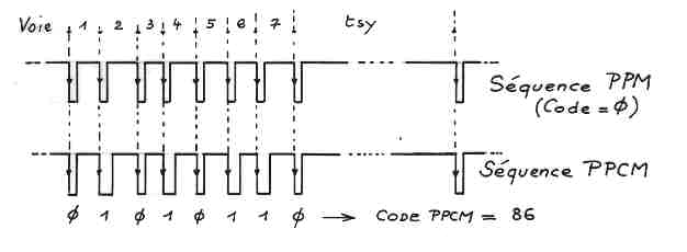
3. The RX19 has an identifying PCM code.
To be considered as " correct ", the received signal must have a " PCM signature ", identifying the transmitter’s owner. This code is a number selected between 0 and 255, inserted in the sequence. It should be noted that we do not use PCM (Pulse Coded Modulation) for the servo’s sequence. In our humble opinion, it only brings useless and even harmful complications, the signal to be transmitted being much more complex. We remain faithful to the PPM (Pulse Position Modulation), a simple and effective method which allows easy insertion of our code. We call this new R/C technique, " PPCM " modulation. The figure above shows the principle used. The great advantage of PPCM is to remain completely compatible with existing receivers, the decoders being sensitive only to the front signal wave, they do not take any account of the position of the rear signal wave and are therefore completely unaware of the inserted code. One can thus, with the same transmitter, control a RX19 (with PPCM) or a RX17 (without PPCM)!
4. The RX19 has an intelligent decoder.
In a normal receiver, such as a RX17 or a RX18, the decoded signal arrives directly at the servos. If the signal is good, all is perfect. If it is bad, so be it and the servos go anywhere and the plane does aerobatics! Let us note how in one such receiver, a fault detector highlights an anomaly only after it has occurred. Obviously! In this case, the servos reacted... and made an inopportune movement... and the plane crashes!
In the RX19, a received sequence is not exploited directly. See below . It is digitized, put in memory, then analyzed.
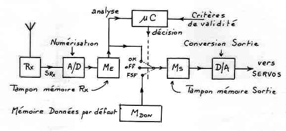 If the result of the test is
good: correct number
of channels, duration
of the time of synchro
in the range exact
PPCM signature...
then the new data
replace the old ones in
the memory buffer to
the servos.
If the test is bad, these
data are not transmitted
to the servos which
continue to use the last received valid data. The result is that the servos
do not make any erratic movement and the plane
does not move. Any erroneous sequence is thus " erased ". The pilot does
not feel anything if that occurs infrequently
(there are 50 sequences a second!). However, if the anomaly lasts more than
35 consecutive sequences, that is to say approximately 0.7 second, the RX19
changes frequency considering Fn glitched and hoping to find on Fs, the other
frequency, a better carrying signal. If it is the case it remains on this
second frequency. If the transmitter is with MANUAL change of
frequency ( i.e. in the HF8 or HF9 modules of SUPERTEF) it is
up to the pilot to note the loss of connection on the emitted frequency and
to change it with the Fn/Fs switch. If this transmitter has an HF10 module
which emits simultaneously on the two frequencies Fn and Fs, the pilot does
not do anything and does not realize anything! The choice of the useful
frequency, at any given moment, is left to the RX19 to better judge on the
matter! The result is spectacular.
A glitch in any phase of flight, even in low passage, full throttle, being
completely invisible!
5. The RX19 has an elaborate FAIL SAFE.
It can happen that the RX19, finds no clear signal on Fn or on Fs. After 5 attempts at shifting frequencies (long fail safe) or 3 (short fail safe), that is to say 2.5 sec. or 1.25 sec. approximately, the RX19 considers the situation dramatic and goes in fail safe, with 4 possible options:
a) Nothing occurs. The RX19 maintains the servos on the last received valid position.
b) HALF THROTTLE Mode. All the servos remain where they are, except the throttle which takes a position programmed by the user according to his desires on the matter. For example, slowed down flying.
c) PROGRAM Mode. All the servos go to positions programmed by the user.
d) EXTERNAL mode. The RX19 uses the output
signal of an external generator of sequence: that can be a simple servo
tester actuating only the gas servo or a complete coder controlling all the
channels, or perhaps an autopilot equipped with gyroscopes, or any
other sophisticated autopilot system, or better still, and how much a simpler
and effective.., an additional receiver receiving at all times the signal
from a safety transmitter! Let us note that this receiver would not need
a decoder. One could for example use the HF section of a RX17-2. This module
measuring 27x32x16 mm, weighing ten grams, consuming 10 mA maximum would
be powered by 4 NiCd cells extracted from a miniature 9V 100 mAh battery
thus giving a 10 hour autonomy!
Note that the external signal provided by the module could have an unspecified number of servo channels. It does not have a code of identification and its direction is unimportant! It is thus possible to use for this connection " of despair " an unspecified unit insofar as it is possible to program it or to regulate it in agreement with the plane to be controlled.
This EXTERNAL mode is an answer to those charming fellows who say to you while laughing: " Sure, a frequency of help… but, what if it is glitching too?? " More seriously, it insures you against a breakdown of the principal transmitter or the HF part of the RX19, a complete jamming of the band (?), a black fly in the eye of the chief pilot…!
Of course, it is not really useful for the old BARON that you fly the weekend,
(although all this hardware would fit inside without any problem) but we
believe that all the " model makers " who fly giant monsters weighing tens
of kilos and worth
a fortune should better concentrate on the source of the problem and replace
an unsuited and perfectly ineffective R/C
hardware in the event of a snag!!
In the 4 fail safe options described above, there is a periodic " update
" of the data of operation. The RX19 thus continues
to scan Fn and Fs with correct values. In addition, let us not forget the
" watchdog " function of the microcontroler. If this
last one loses its program for example, with a violent parasitic storm, 260
ms later, there is a general reset and all starts out again on healthy bases.
As soon as the RX19 finds, either on Fn or on Fs a correct signal, the fail
safe is terminated almost instantaneously. This is useful when teaching a
new person to fly without the need for a special buddy box.
The pupil (or trainee) uses the safety transmitter explained above (his own
transmitter preferably), the additional receiver collecting his signal. The
RX19 is programmed with Fn = Fs. The teacher programs his SUPERTEF on Fn
above, but on a DIFFERENT Fs than Fn. If the SUPERTEF emits on Fn, it controls
the RX19 firstly. If the teacher switches his SUPERTEF on Fs (single frequency
module) the RX19 cannot receive this frequency since it scans on 2 frequencies
equal to Fn. At the
end of 1.25 sec., it passes in fail safe, external mode, which gives the
control to the pupil. The monitor takes back the control instantaneously
by switching SUPERTEF to Fn!!
Training without a trainer cord! Exciting, is it not???
6. The RX19 supervises its input power.
Careful! The RX19 requires a distinct battery from that of the servos. This requirement is related to the frequency synthesis, very vulnerable to FAST variations of the supply voltage. With a single battery and even with a perfectly good regulator, there is always a time when the voltage on a high current servo demand, drops just enough to put the regulator at fault. The synthesis is disturbed and causes a general movement of the servos which causes another voltage drop. It is " the snake which bites its tail "! The system is unable to come out of this situation which goes on until a crash! You can believe our experience which is more than 10 years!
The battery pack of the RX19 can be a 4.8 V / 250 mAh, which ensures a 10 hour autonomy. In addition, the battery of the servos can now be used to its limits without the least problem, except for the reduction of the servo speed. An optional automatic switch would obsolete any other switch and increase reliability since the load is only 25 mA approximately.
The RX19 does not need any voltage regulator then since the very slow and
regular voltage decrease during operation does
not disturb it. This tension can go down to 3 V before paralysing the receiver!
This performance makes it possible to improve the safety of the 4.8 V battery
pack as shown in figure 16: a failing cell is shunted by the diode connected
in reverse, which maintains conductibility while losing 1.4 V approximately.
As one can all the same expect that TWO cells out of four will not weaken
during the SAME flight, one will bring back the plane to the ground safely.
Let us note that the same solution is applicable for the battery pack of
the servos, even if it means using 5 cells, if the servos will take it. It
is also more effective
and less penalizing than to double the number of packs, using an also vulnerable
switching system.
The RX19 checks its voltage continuously. As soon as the battery goes down
to 4.6 V, an external, optional buzzer alarm sounds. The limit of 3 V indicated
above shows that the alarm is set off a long time before the limit of operation.
One can
thus finish a normal flight, without danger, even if alarm can be heard on
takeoff. Notice that with the 10 hours of autonomy, one would really have
to be careless to hear this famous alarm!
7. The RX19 is programmable.
Normally associated with the SUPERTEF, the programming of the RX19 is done by direct cable connection or by infrared similar to a TV or HiFi remote control. You choose on the SUPERTEF:
- the normal frequency
- the safety frequency
- the identifying code...
and the SUPERTEF sends these data to the RX19 in some tenths of a second! In the RX19, the data are received, checked and memorized in a nonvolatile EEPROM memory. They are in safety, for more than 10 years, if one believes the manufacturer of these components ! And we believe it!
9. The RX19 has an 8 channel output.
The SUPERTEF is a PPM, 7-channel transmitter. See the sequence in fig. 14. But an inverter named " Channel 8 " makes it possible to modify the time of synchro, making it go from 8 to 9 ms. An undetectable detail to a normal receiver. On the contrary, the RX19 decodes this information and sends on its output "Number 8" a slot equal to (Tsy - 7) ms, that is to say 1 or 2 ms. It is all that we need for an All or Nothing, 2-position channel.
10. The RX19 has a powerful HF section.
It is perhaps the essential, but let us mention it here because it became almost banal. The RX19 does not owe anything to his/her little brothers, the RX17 and the RX18:
- double frequency converter;
- HF amplifier of input with automatic gain control (AGC);
- 10.7 MHz filter with quartz;
- 455 kHz ceramic filter;
- very low rate of intermodulation;
- maximum integration;
- all SMT construction;
Let us note that the frequency synthesis works remarkably well is completely unnoticeable!
11. The RX19 is easy to build.
Easy...! It is quickly said! Less easy than signing a cheque, obviously!
We simply want to say that the construction of the
RX19 does not pose "electronic problems". It works at the last finished
soldering. There is no calibration problem. It is a healthy, reproducible
assembly reproduced at many specimens… To succeed, one "simply" needs
to be careful, to know
how to solder well, not to shake but to have a minimum of knowledge all the
same. Basic equipment is also necessary: an oscilloscope and a multimeter.
It is the same besides for any assembly of this kind. One does not see the
current passing through wires! If the bench magnifying glass is indispensable
for the assembly and the checking, it is not of any utility for
better seeing... the signals!
12. The RX19 is cheap.
Still a relative remark, of course. Although the choice of the microcontroler
was made to this end. Definitely less expensive
than the 68HC811 MCU of the RX16, it helps decrease the cost appreciably.
In addition, there is nothing else special in the RX19 whose cost would be
higher than that of any other normal receiver.
| Click for REALISATION | 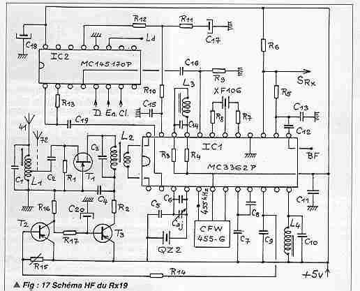 |
| Click for description of rx19b-modif. |
 |