Fig. 1: LC Oscillator on the right fig. 2: |
 |
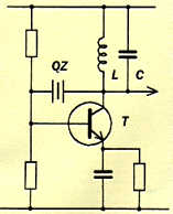 |
Fig. 3: |
 |
|
TRANSMITTERS / RECEIVERS WITH FREQUENCY SYNTHESIS
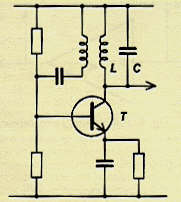
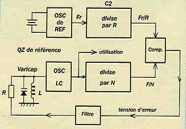
The oscillator (LC) in fig. 1 changes frequency easily, but it " slips ". The quartz oscillator in fig. 2 does not slip, but requires changing the crystals for a modification of frequency. This swapping of crystals, sometimes acceptable depending on regulations, is obviously intolerable if it must be done often or especially if it is necessary to be able to have many different frequencies quickly and easily. The HF electronics specialists were confronted a long time with this dilemma. Fortunately, the spectacular projections of digital electronics allowed, many years ago the categorical resolution of the problem: it is the FREQUENCY SYNTHESIS. It is very simple, we just need to match an LC oscillator and... a quartz. Let us see that in fig. 3.
Fig. 1: LC Oscillator on the right fig. 2: |
|
|
Fig. 3: |
|
|
It all starts with an LC oscillator, admitedly variable but unstable. The
frequency is determined by L and a VARICAP (diode of adjustable capacity by
continuous tension). The generated oscillation F is sent in a numerical meter C1 which
divides it by a given factor N. The output of the meter C1 thus is F/N.
In addition an oscillator with a very stable quartz provides a frequency of
unspecified reference Fr. This frequency is divided by R using a second meter C2 whose
output consequently is Fr/R .
The parameters are selected so that F/N equals Fr/R. For example: LC oscillator on 72250
kHz, divided by N chosen at 14450 giving an output C1 of 72250/14450 = 5 kHz. The quartz
of reference chosen to 8000 kHz, divided by 1600 giving
an output C2 of 8000/1600 = 5 kHz also. Of course, this last 5 kHz is STABLE and
first is UNSTABLE... for the moment!
Let us send the two 5 kHz in a comparator (Cp) able to deliver an error tension of
Verr which duly filtered is applied to the varicap in the PROPER DIRECTION. Then, as soon
as the comparator notes the least shift of phase between the two 5 kHz, itcorrects the
tension of varicap to bring back the frequency F to the proper value. And here is how the
frequency F is LOCKED on the reference Fr. It now has stability and precision. The
corrections are done at the frequency of 5 kHz, which means there are thus 5000
corrections per second!!
Yes, will you say... and to change frequency?
Well, it is very simple. The meter C1 is programmable. Its factor of division N can vary
unit by unit within very broad limits, e.g. from 40 to 65535. For the moment we chose
14450, but suppose that we modify this value by entering 14428. At the initial moment of
the change, the frequency F of 72250 gives the output of C1: 72250 / 14428, which is
5.007624 kHz. The comparator immediately notes the variation of 5 kHz and delivers a
tension of error in consequence, which acting on F, cause
it to drop until arriving at precisely 5 kHz at output C1. But then F became 14428 X 5 =
72140 kHz: our oscillator changed frequency. Let us note that if one modifies by only 1
unit the value N, e.g. from 14450 to 14451, we go from 72250 to 14451 X 5 = 72255 kHz.
Under these conditions, note that the modification of frequency is done in steps of 5 kHz.
It is said that the synthesis step is 5 kHz. It is equal to the value chosen for the
output of the meter C2.
The programming of C1 can be done in parallel, with potentiometers for example but at the
present it is almost always done in series, a micro-controller having the responsability
to manage the operation.
Advantages of the synthesis:
- With only one quartz of reference (and of arbitrary value) one covers ALL the
channels of a frequency band.
- The frequencies obtained have the precision and the stability of the reference. If the
frequency is exact on a channel, it is the same on all.
Disadvantages of the synthesis:
- The band coverage is numerical and nonanalog, which means that the frequency
evolves/moves by increments, by steps and not in a continuous way. That is especially true
for the simple synthetizers. More complex cicuits make it possible to reduce the step to
enough low values to give the illusion of continuity: laboratories’s HF generators,
traffic transceivers, etc. Of course, for many applications, this problem is almost a
quality: in radiotelephones, in our RC transmitters...
Lastly, a disadvantage which perhaps explains the absence of this technology in our RC
hardware: it is a little more expensive!
But the SUPERTEF obviously takes advantage of the frequency
synthesis to the maximum.
It can be equipped with two types of HF modules:
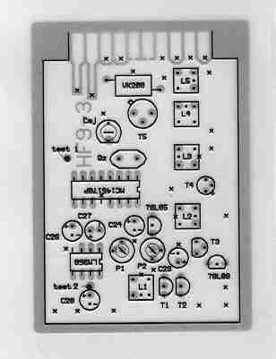
- The HF9-3 module.
It is a MONO-FREQUENCY module , i.e. it emits only on one frequency
The HF9-3 module can be made for 35, 41 and 72 MHz bands. It plugs in
the transmitter like a drawer in a few seconds
The SUPERTEF detects it and programs it on the frequency selected by
the user
- The HF10 module.
It is a TWO-FREQUENCY module: it emits on two frequencies at the same time
* A frequency known as normal (Fn) and;
* A safety frequency (Fs)
Those two frequencies must be on the 72 MHz band.
 |
 |
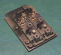 |
Above the TOP and the BACK Left, a HF10 module We can clearly see two
HF modules |