- operating time in h:mn:sec;
- the frequency of emission (when using the frequency synthesis
module)... or "Cf/Qz" for another HF module;
- the tension of the battery pack.
THE SUPERTEF 96
* * * *
INSTRUCTION MANUAL
VERSION V3A
When powering on the SUPERTEF, the coder immediately starts retrieving the data residing in the EEPROM memory of the microprocessor and the EEPROM of the 27C16, namely:
- on the last model used and consequently, on all the parameters programmed for
the 7 channels of this model;
- on the various programmed parameters of operation: various alarms, direction of
modulation...;
- on the last frequencies used by the special HF module with frequency synthesis,
if SUPERTEF is equipped with one (normal and safety frequencies).
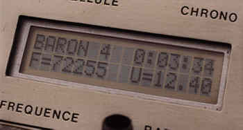
* If the initial configuration above is appropriate to you... don’t change it! At the end of 10 seconds, the initial screen changes to the SCREEN OF SERVICE and displays:
- the NAME of the model used;
- operating time in h:mn:sec;
- the frequency of emission (when using the frequency synthesis
module)... or "Cf/Qz" for another HF module;
- the tension of the battery pack.
* If this configuration is not appropriate to you, you have 10
seconds, at least, to change anything!
I. Model selection
The cursor blinks besides the NAME of the active model. Press on "P". You end
up in the model selection screen. On the left, the cursor blinks beside the model NUMBER
(from @ to Z), on the right you read the NAME of the model. Press on "P", the
cursor does not blink any more and while pressing on "+" or "-" you
can go from one model to another that is to say, step by step, if you push for a short
time the NAME changes at the same as the NUMBER, or in fast mode, if you keep your finger
pressed for a longer time the NAME does not change while the NUMBERS change, but is
brought up to date once you stop pressing. When the desired model is showing, press on
"P" to make the cursor blink, then on "E" to come out of this screen
and go to the menu.
Before pressing "E" to access the menu, you can rename the model. With the
cursor blinking beside the NUMBER, press
on "+", which moves the cursor towards the NAME. Press on "P" to place
the cursor not blinking on the first left character. Change this character using
"+" or "-". Press again on "P" to move to the next
character, then modify it using "+" or "-" and proceed in the same
channel for all 8 characters. When the desired NAME is obtained, press on "E",
which will return you
to the NUMBER, and on "E" again if you are done. The list of possible characters
is , B, C... X, Y, Z, -, 0,1,2... 8,9",
in other words: the letters, the numbers and the characters "space" and
"hyphen".
II. ACCESSING THE MENU
Accessing the menu is done while pressing on "P", during the 10 first
seconds, the cursor blinking beside the model NAME
in the initial screen. You then access the screen for selecting a model, which you can
leave immediately by pressing on "E", bringing you to the MENU. But you have the
possibility of accessing the menu anytime, from the SCREEN OF SERVICE,
by pressing at the same time on both "+" and "-" keys.
The MENU shows seven possible options.
- PCEL: Changing the parameters of the channels for the current model
selected.
- FREQ: Choosing the frequency of emission.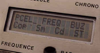
- BUZ: Changing the parameters of the buzzer.
- COP: Copying parameters of a model to another.
- MOD: Changing the HF modulation shift.
- COD: Changing the PCM identification signature coding.
- ST: Calibrating the sticks and the trims.
The "+" and "-" keys move the cursor in the menu and thus change the selection. Confirm selection by pressing on the key "P".
Let us explain the seven options.
1. PCEL
This function allows you to fully adjust each of the 7 channels of the currently
selected model. Version V3A allows MIXING and a COUPLING for each channel. To this end,
the channel has two possible actuators (origins) each one with its direction and its rate.
The two rates are controlled by the programmable DUAL-RATE switches. To these parameters
you can add: "min", "neutral" and "max" making it possible
to set the throw of the servos, the exponential rate and the variance. These last five
parameters being common to both actuators. In addition to the potential mixing permitted
by the two channel actuators
a coupling is also possible. The channel considered as "slave" receiving the
data of another channel known as "master".
All 12 possible parameters are split between two screens : "1" and
"2".
- Screen "1" appears first.
Use "+" and "-" to move in the screen.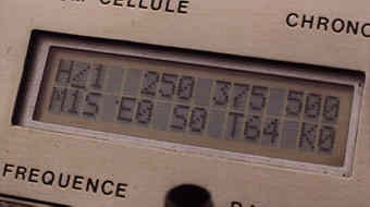
- With the cursor on the last character in screen "1", pressing once more on "+" will lead you to screen "2".
- Going backward within and from one screen to the other is
simply done using "-".
- Programming of one of the 12 parameters is done according to
the "P KEY REMARK".
----------------------------------------------------------------------------------------------------------
P KEY REMARK:
- The cursor moves in the screen using "+" and/or "-" keys.
- To modify a parameter, put the blinking cursor over it and press on "P". The
cursor then stops blinking.
- Modify the value by using "+" and/or "-". A short push increases or
decreases the value of the parameter by 1
unit. holding the key pressed longer causes a fast automatic variation. The
value automatically stops on the limits fixed by
the software.
- Once the parameter’s value is set, pressing again on "P" brings you back
to the blinking cursor.
----------------------------------------------------------------------------------------------------------
N.B. The P key remark explains how to modify a pararameter anywhere in SUPERTEF. It will not be repeated later in the text. Please refer back to instructions here.
SCREEN "1", LINE 1.
* Channel number. It is the number which appears to the right of
"/". Thus for model A you can scroll through A/1 to A/7. This number represents
the receiver channel number. Therefore, channel 1 is coming out of connector # 1 on the
receiver’s block of connectors. As such, this number has nothing to do with the stick
number. However, to facilitate data entry on the first time, channel 1 is the same as
stick 1, channel 2 is the same as stick 2, etc. When one changes the channel number (as
explained in the P KEY REMARK), all the other displayed parameters are those of the
selected channel. The complete programming of a model will have thus be done, channel by
channel.
* MIN, NEUTRAL, MAX. These three independent parameters adjust the channel trims. The displayed values correspond to 1/4 of the final duration in microseconds. By default, the values are preset to 250, 375 and 500 points, which gives 1000, 1500 and 2000 µs. Adjustments can be done by simply looking at the values on the transmitter display but it is much better to do so by observing the effective action on the control surface itself. However, in this case, we advise to use the following method:
- Always start adjusting the NEUTRAL trim. All sticks in neutral position. Observe well the direction of displacement of the control surface when increasing (or decreasing) the parameter. Do this even if the neutral does not need to be corrected, in order to know the direction of movement!
Example: The control surface goes to the right by increasing the neutral parameter. We can then deduce that the end point "on the right" corresponds to the MAX setting.
- To adjust this end point "on the right" (as in the example), move the stick
in the proper direction to its fullest. Then adjust the MAX throw parameters to bring the
control surface to its desired position.
- Push the stick fully in the opposite direction and adjust the MIN parameter.
The observation of the direction of action is of primary importance, because it avoids programming an end point by putting the control surface in the wrong position, since the parameters MIN and MAX are independent of each other.
LIMITS of MIN, NEUTRAL and MAX
a) The minimum value of "MIN" is fixed at 200 points (800 µs), to permit a
good transmission of the impulses in PPCM modulation.
b) The maximum value of "MAX" is fixed at 600 points (2.4 ms), sufficient cover
all possibilities.
c) The three parameters, MIN, NEUTRAL and MAX can evolve/move in this range (200 to 600)
by respecting the following constraints:
- the MIN valuemust remain lower than NEUTRAL
- the NEUTRAL value must remain lower than the MAX
- the difference between MIN and NEUTRAL on the one hand and NEUTRAL and MAX
on the other hand, cannot exceed 240 points. In this case, at least 15 points of freeplay
are left for the trim. Indeed, registers A and B of the µP can only handle 8-bit numbers,
that is to say, less or equal to 255.
Examples: if you program: - > MIN = 250 and MAX = 520, the NEUTRAL will be able to evolve/move between 520 - 240, either 280 and 250 + 240, or 490. If you program: - > MIN = 300 and MAX = 530, the NEUTRAL could evolve/move between 540 - 240 thus 290 and 300 + 240 = 540, but it will only be able to do so between 301 and 529, not being able to exceed neither MIN, nor MAX. In spite of these inevitable limitations, we think we can thus satisfy all those who have a particular trim requirements.
SCREEN "1", LINE 2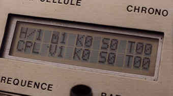
* ORIGIN 1. (Displayed as Mx).
It is the number of first actuator
of a channel. Thus channel 1 can have stick 1 for origin, but also
any other stick. An example: The TF6 and TF7x always had the
gas channel in second position. With the SUPERTEF, configured
by default, you will have it in 4th! If you wish to change it to its
original position, you simply have to program for channel 2 an origin
equal to 4. Note however, if you permute the origins we advise you
to draw a diagram of it on paper, so as to avoid a confusion, source
of impatience and panic! In the case above, that would give:
| Channel | Origin | Affectation |
|---|---|---|
1 |
1 |
Ailerons |
2 |
4 |
Gas |
3 |
2 |
Elevator |
4 |
3 |
Rudder |
Two channels, or more, can have the same origin. That allows what we call a
"coupling by the origin"! Two servos can then be connected on different receiver
channels, while being controlled from the same stick.
One can use the same possibility to obtain differential with the ailerons, two channels
actuating the right and left servos, under the effect of the ailerons stick 1, but with
different servo travels.
* VARIATION. (M1x). Parameter common to both actuators. The variation
has a triple role:
a) Memorization type of the "c" value of a master channel
(see the section titled ‘Parameters of the master channel’).
b) Choice between the trim with 12.5% (lower case letter) and the
trim with 25% (UPPER CASE LETTER)
c) Action on the SLOW function (sticks 4 to 7) One will refer to the
paragraphs COUPLING, TRIMS and SLOW for more details on this subject.
* EXPONENTIAL. (Ex). It is the possibility of having on a command, a low effectiveness in the vicinity of the neutral and a much larger effectiveness at the extremes. The total throw remains available, which is not the case, during the use of DUAL-RATE. The rate of exponential can vary from 0 to 8. Change according to the P REMARK, but only by small increments. A value of 5 is preset.
Caution: The exponential parameter set will be common for both sticks used on the channel.
In addition, the exponential is active only if the declared origins are 1, 2 or 3. Actuators 4 to 7 do not have exponential functions EVEN IF one of the value is set higher than 0, on the other hand, in this case, the value of EXPO determines the operating mode of the SLOW. See that paragraph for more details.
- SERVO 1. (Sx) It sets the direction of displacement of the control surface, according to the displacement of actuator 1 (origin 1). If the parameter is worth "0", the direction is known as normal. If the parameter is worth "1", the direction is reversed.
The adjustment is made according to the P KEY REMARK, except that the action of the "+" and "-" keys is identical. The change of direction is immediate on the model selected.
- RATE 1. (Tx). The throw is fixed by MIN and MAX, but it is possible to use only one fraction varying from 0/64 to 64/64 by programming the "rate" parameter. The parameter RATE 1 thus makes it possible to reduce the throw of a channel, during the handling of actuator 1. However the application of RATE 1 is related to the position and the programming of the DUAL-RATE switches. Indeed, as we will see it in the following paragraph, it is possible to choose the number of the active switch, even remove the action of these switches.
Example: Channel 1 --- > Rate = "32" is 32/64 = 1/2
(stick n° 1) MIN = 250 --- > 1000 µs
NEUTRAL = 375 --- > 1500
µs
MAX = 500 --- > 2000 µs
If DRx = OFF --- > Throw from 1000 to 2000 µs
If DRx = ON --- > Throw from 1250 to 1750 µs
If rate 1 of channel is "64", the tumbler selected is inactive.
Aside from the DUAL-RATE, the "rate" parameter is necessary during the mixings.
Indeed, in this case, the actions of two different sticks, are added in a same channel. It
is thus essential to reduce the action of each one of them, to avoid a significant
saturation, at the time of simultaneous actions. It should be noted that the software
automatically limits the throw to MIN and MAX, in the case of an excessive action.
- DRx Switch. (Kx).
This parameter related to actuator 1 makes it possible to control the effective
application of RATE 1.
- value 0 removes the action of any DRx switch.
- values 1, 2 or 3 give to DR1 or DR2 or DR3 the control of
RATE 1. It becomes thus possible to carry out a mixing without fearing blunders from
handling the switches, or tosimultaneously control several channels with the same DRx
switch.
SCREEN 2, LINE 1
Line 1 of the second screen makes it possible to program all the parameters relating to the effectiveness of actuator 2 of the channel considered.
One thus finds there
- ORIGIN 2, noted mx, allowing the choice of actuator 2.
Version V3A makes it possible to give to this origin 2 a value of "A"
to "G", with the following correspondence:
1 |
2 | 3 | 4 | 5 | 6 | 7 |
A |
B |
C |
D |
E |
F |
G |
In this case, actuator "1" to "7" is active, but its action is unidirectional, moving the control surface from the NEUTRAL to the MIN, or from the NEUTRAL to MAX only, for a total displacement of this actuator. The choice of the direction of action (towards the MIN or the MAX one) is obtained by "SERVO 2".
- the K switch allows the choice of which DRx will control the rate.
- SERVO 2 determines in which direction the
servo will move when actuator 2 moves.
- RATE 2 proportions this movement according to
the DRx switch.
CAUTION: The action of switches DR1, DR2 or DR3 is different from that which we saw for
the DUAL-RATE.
With regards to the MIXING :
- > If the switch is "ON", the programmed rate is applied.
- > If the switch is "OFF", the ACTION of STICK 2 is CANCELED.
The action is thus identical to that of the switches for coupling, which we will see below. Refer to the paragraph "SCREEN 1, LINE 2" for more details. Recall that VARIATION and EXPO operate actuator 2 as well as 1.
The possible action of two actuators on the same channel allows various configurations of this channel:
- SINGLE CHANNEL. Simply program:
Rate
1 > 0 with Rate 2 = 0 or Rate 1 = 0 with Rates 2 > 0
In the first case, only actuator 1 is active. A rate lower than 64 will be applied,
according to DRx to the action STICK, but NOT to the TRIM. Make this selection for a
channel with DUAL-RATE, if you wish that the reduction of servo travel does not modify you
throw settings. In the second case, actuator 2 is active. A rate lower than 64 will be
applied, according to DRx, AT THE SAME TIME to the action STICK and the action TRIM. It
can be useful for certain special effects.
- MIXING. Simply program: Rate 1 > 0 and Rate 2 >
0
The two actuators are then simultaneously active, each one with its own parameters, but
with EXPO and VARIATION common, without forgetting MIN, NEUTRAL and MAX. It is necessary
that RATE 1 + RATE 2 not exceed 64. If not, at the time of a simultaneous full action of
the two sticks, the servo travel end points will be saturated but without any negative
effect though because the software always limits those to MIN or MAX.
SCREEN 2, LINE 2.
This adds COUPLING to the channel in question.
Coupling makes it possible to inject into a channel known as "slave",
commands of another channel known as "master". The "master" channel
affects, in addition to its own control surface, the "slave" control surface.
The opposite is not possible when programming only a simple coupling.
The coupling parameters of a "slave" channel are:
- the ORIGIN, defining the master channel number. Note that this
origin is noted Vx, to remind ourselves that the added effect comes from a channel and not
from a stick .
- SERVO travel direction of the coupling, making it possible to have the
same direction as that of the master channel (S=0) or the contrary direction (S=1).
- the RATE of coupling, defining the importance of the action
"master" on the channel "slave", varying from "0" to
"64".
- the Kx SWITCH controls the effective application of the coupling. They
are identified as CPx switches, for "coupling". One can define, at most, seven
simultaneous couplings, that is to say 1 per channel. For that, it is necessary that the
"slaves" channel values be different than "0".
Three SWITCHES can activate the couplings if they are ON or not if they are at OFF: CP1, by programming "K1", CP2 using "K2" and CP3 using "K3". By programming "K0", the action of the switches is PREVENTED.
Parameters of the MASTER channel
Each of the 7 channels of SUPERTEF can be a "master channel", which means that it can act on another channel known as "slave". To this end, during the phase of calculation of the time of a channel, a number equal to the difference between the current value of this channel and the neutral are memorized for possible use by another channel. This calculation takes place whether the couplings are used or not, because the master channel "does not know" if another channel will be its slave. The memorized number can be represented by the formula: c = Y - N in which "c" is this quantity, Y is the current value of channel and N is the neutral.
"c" is positive or negative according to direction's of displacement of the
stick. Actually, several values of Y follow one another during the calculation of channel
- YP, or weighted time of channel, after application of the
RATE
- YF, or FINAL time of channel, after COUPLING and
limitations.
In the same manner, there are two neutrals:
- nS, or STATIC neutral: it is the value programmed
- nD, or DYNAMIC neutral, after application of the trims.
Recall, the second parameter of line 2 / screen 1: "the VARIANCE" given by a
letter "s", "t", "u", "v", "w",
"X" or the same ones in upper case!
If you enter "s" there is memorizing of c = YP - nD, that is to say the channel
gap without the trim.
If you enter "t", memorizing will be c = YP - nS, a value taking account the
trim.
Note that, with "s" and "s", the quantity "c" does not
contain the result of a coupling since the calculation of the time of channel takes
account of it only afterwards.
If you enter "u", there is memorizing of c = YF - nD, a quantity containing the
effect of a possible coupling. Under these conditions, the affected channel of this
"u" can be at the same time slave and master and gives CASCADING couplings.
Example
Channel 1: Variance s CPL - > O 1 S 0 T 00
Channel 2: Variance u CPL - > O 1 S 1 T 40
Channel 3: Variance s CPL - > O 2 S 0 T 32
Channel 2 is slave of channel 1 and master of channel 3.
As the variance of 2 is "u", channel 3 will be sensitive to channel 2 but also
to channel 1, master of 2.
In channel 2, you will have 40/64 of 1 and in 3, 32/64 of 2, that is to say 1/2.
In channel 3 there will be then 1/2 of 40/64 of 1, that is to say 20/64.
If you enter "v", there is memorizing of c = YF - MIN
If you enter "w", there is memorizing of c = YF - MAX
For instance, these two variances allow unidirectional couplings for air-brakes or flaps. Note that "w" gives the opposite direction from "v", which makes it possible to solve certain problems more easily.
If you enter "x", there is memorizing of: c =
absolute value of (YP - nD)
thus an always positive value, whether the channel master goes in a direction or in the
other.
All that becomes a little complicated and thus is only applicable to particular applications which the average model maker does not need. Is it not less true that "which can do more, can do less"!
Parameters of the SLAVE channel
The rate of coupling varies normally from 0 to 64, or from null coupling to maximum
coupling. When the rate is programmed, one can only choose between the null coupling and
the value selected, insofar as a coupling switch was selected. It is thus not possible, in
theory, to program a coupling while "in flight".
Version V3A has this possibility: during programmation of the rate of coupling, the rate
can exceed the maximum value 64, to reach "65". Under these conditions, the rate
does not regulate the coefficient of coupling but the position of the auxilliary
proportional 5. While operating this potentiometer, the coupling goes from null to
maximum!
This situation can be permanent, if it is appropriate to you, or simply provisional, to determine the best value to adopt for the final rate. If it is the case, once the proper adjeustment of 5 is found, go to "St" and read the value of the stick #5. Divide by 4 and you have the proper value to program. Nothing prevents controlling several couplings by M5 at the same time, if that is useful.
N.B. Because you can now simply go from 64 to 65, using the key "+", it is necessary to be very attentive to this limit, "64" and "65" giving completely different results!
N.B. One returns from "65" to "64" by simply using the key "-".
In conclusion, it is important to include/understand well the action of the parameters
of coupling:
- Origin, servo direction and rates of coupling are used by the
channel, when it is declared "slave" by a rate different from "0".
- the VARIANCE parameters "s" to "x" are used by
the channel, with a goal of possibly playing a role of master.
The modification of this VARIANCE is done quite simply like that of any other
parameter, as explained in the P KEY REMARK.
Actually, the complete string of the variances is "stuvwxSTUVWX". At coupling
level, the upper case letter has the same effect exactly as the small case letter. One can
thus choose one or the other. We will later see that the difference in action is at the
rates of trim level or the SLOW effect.
Of course, in addition to the potential mixing available for each channel using the two
actuators, it is always possible to program others by the method of the crossed coupling,
the only way available in the preceding software versions. It is assumed that under these
conditions, few configurations must still be unsolvable!
TRIM RATE
The effectiveness of the trims of sticks 1, 2 and 3 can be set to 12.5 % or 25 %. To
choose between these two values, it is necessary to put the VARIANCE of coupling of the
channel using the stick and thus the affected trim, either into small case, or in UPPER
CASE:
- If the variance is a small case letter "stuvwx",
the trim is set to 12.5 %.
- If the variance is an upper case letter "STUVWX",
the trim is set to 25 %.
One can mix different rates of trims on the various channels of a model, without any
disadvantage. For example, you can set the trim to 25 % on ailerons and rudder and to 12.5
% on the elevator.
The channels which do not use sticks 1 to 3 do not have a trim. Under these conditions,
the variance has no effect on this level.
SLOW Function
This function slows down the movement of the servos, useful in certain cases, as when flaps are deployed. This function is rather elaborate since it allows you 4 speeds of SLOW, in one direction or the other exclusively, or in both directions. The function SLOW exists only for the channels whose "M" origin in the second line of the first screen is 4, 5, 6 or 7. SLOW is programmed with the parameters EXPO and VARIANCE, by giving the results summarized in the following table :
| VARIANCE | EXPO | - <-- SLOW --> + | |
|---|---|---|---|
| UPPER CASE | Even number | Yes |
Yes |
| UPPER CASE | Odd number | No |
Yes |
| lower case | Even number | Yes |
No |
| lower case | Odd number | No |
No |
| Other | 0 |
No |
No |
Note: An UPPER CASE lettered VARIANCE decreases the speed of the function SLOW while a small case increases it. An EVEN numbered EXPO decreases the speed of the function SLOW while an ODD number increases it.
One can choose 4 speeds of SLOW by varying EXPO from 1 to 8. The following table gives the approximate duration obtained for a full servo travel (90°).
| EXPO | Time for full servo travel |
|---|---|
1 or 2 |
0.65 s |
| 3 or 4 | 1.25s |
| 5 or 6 | 1.85s |
| 7 or 8 | 2.5s |
If a channel programmed with the function SLOW is used as a MASTER channel in a coupling, the SLOW will only be active in the SLAVE channel, if the VARIANCES u, v, w, U, V, W are entered in the parameters of the MASTER channel. If you enter the other VARIANCES s, t, x, S, T, X, the SLOW is disactivated in the SLAVE channel.
EXITING from PCEL
You exit by pressing on the "E" key. This is valid for going back to the MENU
after programming any of the seven main options (see ACCESSING THE MENU). But at this
moment, all the data which were modified in RAM (random access memory), will be
transferred in EEPROM, so as to be available at the next power up.
When pressing on "E", you will see the transfer "the error screen". If
your system is in working well, there will always be zero "0" error. This
indicates that the data transfer was well carried out. The day when you will have an error
count other than zero, it will be necessary to consider servicing the SUPERTEF. We hope it
won’t be soon!
To leave the error screen and return to the menu, press on "E".
When exiting any model saved in the memory slots I to Q, you will have to answer the
question : "NOMBRE de CELLULES ASSOCIEES". Entering "0"
deactivates switches CONFBIS and CONFTER, while entering "1" activates CONFBIS
only and entering "2" activates both CONFBIS and CONFTER.
2. FREQ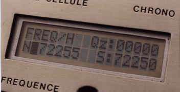
This function is used to program the frequency of emission, in the case of the use of a special SUPERTEF module with frequency synthesis. When a non-synthesized module in inserted, the FREQ function is unavailable. Each model may have two frequencies: Fn and Fs (normal Frequency and safety Frequency). We can thus program in memory 2 X 27 frequencies per band. Fn is obtained by putting the side tumbler marked Fn/Fs on Fn, therefore with the contact of the switch open. Fs is accessible by closing this contact, therefore by rocking the tumbler on Fs, that is to say normally forward.
At the beginning, by default, all 54 models are on 72250 kHz or on 41100 kHz depending on the band of the inserted module.
Programming
At the entry in routine "FREQ", the display indicates on the first line the
frequency chosen for the quartz of the down-mixer for module HF8. Once the module is
installed in Supertef, you will not be able to change this value. The technical details of
this installation are given in the description of HF8.
Go to the first line titled "Quartz", using the "-" key and return to
the last line called "Frequency", using "+".
In module HF9/10, the down-mixer is removed and there is no quartz inside. The screen
indicates "00000", a nonprogrammable value.
In any event, at the start, the cursor is located on the second line and on the normal
frequency announced by "N:xxxxx". One can go to the safety frequency marked
"S:xxxxx" by pressing "+" or return at the normal frequency with
"-".
Programmation of the frequency is done according to the the P KEY REMARK. Modifications
are done in steps of 5 kHz.
The effective frequency of emission is changed only after exiting the routine and not during the programming.
If you programmed different values for Fn and Fs, you will exit by going through a screen of validation, which will bring you to the MENU if you accept the two values or returns you to the previous screen for changing the frequencies again. Of course, one should choose two different frequencies only if the associated receiver is likely to accept them. It must thus be a question of a model with on-the-fly frequency shift, either REF10, or RX16 or RX19.
The accessible frequencies are limited at the legal boundaries of the exploited tapes, the software blocking the advance or the retreat when the limits are reached.
3. BUZ
This screen displays the parameters of the operating modes
of the buzzer.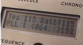
a) Tps
Alarm signalling the "flight time". Can programmed from 0 to 59 minutes. At the end of the programmed time, the buzzer resounds during 5 seconds. In the old version with 6 model memories, the programmed time is common to all the models. Programming a null time (0) removes any alarm.
b) Batt
Low battery voltage alarm. Can be programmed from "50" to "130", which corresponds to 5.0 and 13.0 volts. With a 12 volts battery in the SUPERTEF, a reasonable threshold is 11.5 V, that is to say "115". When the threshold is reached, the buzzer will sound continuously, by short streaks.
c) PLL Threshold
The default values are appropriate in general. Do not change them. If the tension of varicap in the module comes out of the limits fixed, the alarm will sound continuously.
LEAVE BUZ by pressing on "E" to return to the menu, via the error screen.
4. COP
This menu function allows you to copy the data from one model memory to another. The Source Model and Destination Model numbers can be selected, using the usual method. Note the direct passage of Z to @ and @ to Z, while incrementing and decrementation. By default, the two numbers are those of the current model selected. Thus, if you entered that routine by error, exit by pressing E. There will be no copy done since the software only allows the copying of data if the two numbers are different! Once the numbers are defined, pressing on E exucutes the copy and exits by the error screen. This function is especially useful for models when you want to change of configuration in flight. See further down. One thus can, at the beginning, make the two configurations identical, while bringing later, the final improvements justifying the change of configuration. Other use of this function: if, for an unspecified reason, one of your model has parameters "screwed-up", the copy function will avoid you a complete reprogramming of the microprocessor.
5. MOD
This function allows the user to choose the direction of the modulation shift. When
entering this function, a screen indicating "SUPERTEF" and the reference of the
version of the software "Vx.x" is displayed, then the cursor is placed on the
direction of the modulation: 0 or 1
Also note the indication "S/Md/x" where "x" is the current model.
Indeed, each model can have its own direction of modulation.
- For all the FM "THOBOIS" receivers, the direction required is "0",
giving negative shift signal impulses of 300 µs, for both HF8 and HF9-1 modules. It is
"2" for the more recent HF9-2 and HF10 modules.
- For other manufacturer’s receivers, it may be necessary to use a reversed direction
of modulation "1", giving positive shift signal impulses, this with HF8 and
HF9-1, or "3" with HF9-2 and HF10 modules.
This possibility increases the scope of SUPERTEF while making it compatible with almost
all PPM receivers and all HF modules created to this day!
Modifications to the directions are done by following "the P KEY REMARK",
without fast advance.
LEAVE by pressing "E".
Press again on "E" to return to the menu.
CAUTION: The modification is effective, only after completely exiting
the MENU!
You will not note
anything after pressing "E" only.
The memorization of the new direction of modulation is linked to the continuous system
of verification of the validity of the work of the µP. It is the system’s
"WATCHDOG". Here, the software notes that the effective direction of modulation
is not the same as what was programmed, since it has been modified. It thus starts a
"watchdog" RESET which sets all to 0 and reboots the system upon re-examined and
corrected data. It is a very important safety feature guaranteeing that if the µP is
temporarily disturbed, it will recover itself, that within a time so short that the user
will not even realize anyyhing! It will therefore not be possible to crash the µP!
This is the best safety insurance for all owners of a SUPERTEF!
BE CAREFUL also to choose the correct modulation shift according to the TYPE of HF module
used. An error prevents the locking of the PLL and causes an alarm buzzer.
6. COD
This function allows the user to select between traditional PPM and our own PPCM
signal. The possibility of "PPCM" modulation is included in version V3A. It is a
traditional "PPM" modulation, but with a "PCM" signature. We found
amusing to call it "PPCM"!!
The process, undoubtedly completely new, consists in transmitting impulses of 300 or 500
µs. An impulse of 300 µs accounts for "0", while that of 500 µs accounts for
"1". As we have 8 impulses in the signal of 7 channels, we can thus transmit a
binary number going from "0" to "255". This number is the CODE for the
PCM signature. You can in effect program it choosing the function "Cod".
Our PPCM modulation has the great advantage of being perfectly compatible with all the
existing traditional decoders. Indeed, these decoders are sensitive only to the fronts
faces of the impulses, being unaware of their duration. On the other hand, let us point
out the existence of the REF.10 which can receive PCM coding and use the process we call
"on-the-fly frequency shift", in partnership with the double frequency available
to SUPERTEF.
New RX16 and RX19 receivers also obviously use PCM code.
The programming of PCM identification signature coding is done according to the the P KEY REMARK. The user must choose a unique and personal and keep it for all models equipped with a REF.10 or a RX16 or a RX19 receiver. One cannot have a different code for each model. By default, the code is "000", which is equivalent to PPM modulation. There is no disadvantage in using a code different from 0 with an ordinary receiver: the latter will see no difference here! Nevertheless, if you do not use a receiver with on-the-fly frequency shift like the REF.10, the RX16 or the RX19, there is no advantage to changing this code from the default. With the SUPERTEF 96, if the frequencies Fn and Fs are IDENTICAL, the PPCM code emitted will always be "0" whatever the programmed value. Indeed, this PPCM code is only useful for the receivers with on-the-fly frequency shift.
7. ST
This function is used to calibrate the sticks and the trims. The screen displays the
numerical value of the four sticks M1, M2, M3 and M4 and of three trims T1, T2, T3. M1 and
T1 correspond to stick 1, M2 and T2 to stick 2, M3 and T3 to stick 3. Under the value M4
of stick 4, one reads M5 the value of command 5 of the auxilliary with a rectilinear
potentiometer.
As already noted before, the value T4 does not appear since it is directly mixed with M4.
The values M1 to M4 are especially useful at the time of the first startup of SUPERTEF,
and thereafter, for verification purposes:
- For the neutral, it is necessary to read "128" plus or
minus 2 points (126 to 130)
- The end throws should be "0" and "255". It is
very difficult not "go beyond" the end throws since perfect potentiometers do
not exist!
The values T1 to T3 of the trims of sticks 1 to 3 allow a perfect setting of the
neutrals of these commands, using a value of 128 + / - 2 points, in conjunction with the
function "Neutrals Memorization" explained below.
The value M5 is useful when it is associated with a rate variable coupling value of 65.
See above.
LEAVE ST/CAL by pressing on "E" to return to the menu.
III. EXITING the MENU
- Press on "E".
- A screen pointing out the origin of the software used is
displayed during 2 seconds
- The program exits automatically and returns to the screen of
service
- After exiting this menu you can return there anytime pressing
at the same time on the keys "+" and "-".
IV. NEUTRALS MEMORISATION
This function was included because it seems useful! As we will later explain, you
should not abuse it!
When flying a model for the first time, the pilot presets the control surfaces with the
"physical neutrals" of the plane: ailerons well aligned with the profile, rudder
well in the axis...
However, in general, these settings are modified as of the first moments of the flight due
to inevitable imperfections of the model and incorrect setting of the neutrals. The pilot
uses the trims to do these corrections. Each model saved will then have different
adjustments for the trims which poses a problem when switching from one model to another.
The NEUTRALS MEMORISATION tends to alleviate this disadvantage!
At the end of the first flight, without touching the trims and before turning off SUPERTEF, press on "E" and simultaneously press on "P" then let go! At this moment, the adjudments made during the flight to the neutrals neutrals will replace the neutrals which you had programmed with "PCEL". Therefore, next time you fly, you will have the same positions of the control surfaces after setting the trims to the exact neutral, using the function "ST". Under these conditions, all your models will be able to fly with the trims in neutral!
NB: Of course, you should not misuse this possibility and carelessly set a model pretexting you will be able to correct problems with SUPERTEF.
Do not forget that a plane flies well if it is physically sound! If the differences between the actual plane neutrals and the programmed neutrals are too significant, your radio is surely badly adjeusted and it should be corrected or at the very least, to try to do better ... next time!
== > When exiting neutral memorization, if you are in a basic model having authorized Bis/Ter configurations (models I and Q), you will haveto answer whether you wish an automatic memorizing of the neutrals of these associated models bis/ter. It seems logical to answer "yes", but you can also answer "no"!
V. TACHYMETER
To access this function, it is necessary to have a special TACHYMETER module plugged in the DIN socket of SUPERTEF. When the strap PC7-3/PC2 of the connector male is plugged in, a special screen appears. While directing the module towards the propeller of the model, you will be able to read the number of rotations/mn of your engine. The TACHYMETRE module has a switch to choose between two blades and three blades propellors. Automatically EXITS by disconnecting the optical sensor.
VI. TELECHARGEMENT (DOWNLADING)
The function of downloading allows a bidirectional communication between two SUPERTEFs
or between a SUPERTEF and a PC. This communication has two purposes:
- one, to exchange interesting programs between two SUPERTEFs
or to synchronize two SUPERTEFs in view of training;
- two, to connect SUPERTEF to a PC using SIMULTEF, a software
application as its name indicates, simulating the operation of our transmitter by showing
on the PC the effective action of the sticks on the servos.
SIMULTEF displays, side by side, the 14 programming screens of a model which gives a global vision of the situation, impossible with the modest LCD screen of 2 lines of 16 characters of SUPERTEF. One can modify all the parameters easily and thus quietly study the results of such and such weird coupling or other mixing!
Once the programming of the model is completed on the PC, one could be satisfied to "manually" copy the various values defined for each of the 7 channels in the SUPERTEF, by calling "Pcel". But SUPERTEF "that nothing stops" will do much better!! A cable connecting it to the PC will send directly in memory all the data in a few tenths of a second!
By connecting the cable to SUPERTEF a special routine of transmission of data named " RS232 " is called. A first screen makes it possible to choose between the "reception" (press on +) or the "transmission" (press on -), you can also exit the routine by pressing on E. If you choose the "reception", a first data loading places the info in working RAM. A second loading checks the validity of the first and shows the result on a screen counting the errors. Leave this screen by pressing E and write the data in EEPROM by pressing E again if all is well or abort the procedure by pressing on P. The procedure will be aborted if the number of errors is greater than zero. You can also abort the procedure if you see that the data loaded in SUPERTEF is not want you wanted. Five successive screens indicate what actions to do to carry out the routine. Leave the error screen while pressing on "E".
The last screen indicates that aborting the routine is obtained by pressing on "P" while saving the data is done by pressing on "E". In both cases, you are taken back to the initial screen of the RS 232 routine. In the case of data "transmission", you will have to make this operation twice at the request of the data receiver, either the PC, or the other SUPERTEF. Return each time to the initial screen. When exiting routine RS232, right before pressing on the key E, do not to forget to disconnect the connecting cable, or else you will immediately return to the routine, which can take you by surprise!
Note that the software program SIMULTEF was created by Mr. André AMYOT. SIMULTEF is much better on a color VGA or EGA monitor and is much easier to use with a mouse. Under these conditions, it is a very powerful software, allowing the bidirectional connection with the SUPERTEF, the memorizing of 80 models, without speaking about the dynamic study of the program or of the printing of data cards for each model...
The connection between two SUPERTEFs requires only one cable made of two wires, while a PC connection requires a module of adaptation RS232 which was described in the general construction article.
Case of the RX16 / RX19
The RX16/19 receivers are using frequency synthesis and on-the-fly prequency shift. Their two working frequencies Fn and Fs and their PCM code are programmable through SUPERTEF either using a connecting cable, or by an infra-red link. In both cases, the connection of the transfer module triggers the downloading routine in SUPERTEF. Pressing on "P" prepares the transmission which will be fully carried out only when pressing on "E".
SUPERTEF then sends Fn, Fs and the PCM code chosen, these data being recorded by the RX16/19 for immediate use.
VII. CHANGE of Configuration in Flight
The SUPERTEF’ 9 BASE memorised models can be setup to have two copycat models each which can be accessed painlessly in flight by simply pressing on the switches called CONFBIS and CONFTER. This is especially useful when a pilot has programmed a normal, sharp and easy behaviour for each 9 possible models.
The 27 models are then divided into three groups:
- Models @ to H, models I to Q and models R to Z
- the two groups @ to H and R to Z, or 9 + 9 memories, are
SIMPLE memories without any Bis configuration.
Actuating the CONFBIS or CONFTER tumblers will have no
effect.
- the 8 memories of the group I to Q are BASE memories, with BIS
and TER configurations.
They are linked with the 9 last models which are BIS and with
the 9 first ones which are TER.
The links are set in triplets according to the following provision:
| TER | BASE | BIS |
|---|---|---|
@ |
I |
R |
A |
J |
S |
B |
K |
T |
C |
L |
U |
D |
M |
V |
E |
N |
W |
F |
O |
X |
G |
P |
Y |
H |
Q |
Z |
Switch from the BASE model to the BIS, while pressing on "CONFBIS".
Also switch to TER by pressing on CONFTER whether CONFBIS is pushed in or not.
== > This change is possible after the first ten seconds and while in the MENU.
This new function makes it possible to test instantaneously, in flight, the
modification of a parameter of the model, or to change the behavior of the model (from
sharp to easy for instance!) It makes it possible to avoid modifying the Dual-Rate or
couplings, which are not always easy to reach during piloting.
Note that the frequencies of the base models, therefore I to Q are not affected by the
change of configuration. Same for the polarity of modulation. That, even if the BIS and
TER models have different values at this level.
The models @ to H and R to Z can also be programmed as autonomous base models. The
possibilities of keeping in memory 27 completely different planes in SUPERTEF are thus not
reduced. These models cannot be changed in flight using CONFBIS and CONFTER, this
restriction being voluntary to eliminate any risk from false maneuver.
If you save the trims of base models I to Q, a screen reminds you that it should also be
saved for the bis/ter, if bis/ter there is! This memory save is automatic if you give your
agreement.
SECURITY: when exiting the programmation of a base model with configuration BIS/TER ( I to Q ), you are asked whether you authorize these configurations. For that, a screen asks you for the "Number of associated models". If you answer 0, there will be neither CONFBIS, nor CONFTER for this basic model. If you answer 1, the CONFBIS alone will be authorized, keeping line PD0 inactive. If you answer 2, the CONFBIS and CONFTER will be activated.
It is the P key which allows changing the choice 0..1..2..0..1....
The E key records the choice and brings you back to the MENU.
This security makes it possible to avoid any blunders!
VIII. STOP CHRONO
After the request of the amateurs of electric flight and towed sailplanes, we added the possibility of stopping the advance of the timer. In order to achieve this, two things must be done :
a) Close a side switch called "STOP-CHRONO"
b) Set channel 7 in such a way that the difference between its
channel time and the programmed value are positive or negative, according to selected
direction. Of course, channel 7 can be controlled by any stick, by defining its origin.
The direction of the stopping of the timer depends on the programmed direction of the
channel AND the programmed direction. The exact stopping point of the timer is
programmable, as well as the direction of this stop.
Here is the process to follow:
- Give to channel 7 a proportional origin, for example,
"5"
- Position this command at the point of desired stop
- While being in the SCREEN OF SERVICE
press on P and +
to memorize the point of stop and the direction
P
P and - to memorize the
same point of stop and the contrary direction
- Go through the error screen. Exit towards the MENU
- Reprogram channel 7 to its origin.
The process thus proves of a great flexibility and can adapt to each particular case,
while exploiting the direction of channel 7 combined with the programmed direction.
CAUTION: For a normal operation of the STOP CHRONO function, it is essential to go through
the above process at least ONCE.
Recall that the timer controls the function of waiting of the 10 first seconds during
which one can choose the model or go to programming mode. If the function of STOP CHRONO
would happen to be active during those first 10 senconds, the timer would stop at the end
of this period on the value "0:00:10", which is likely to frustrate some users!
To avoid all "frustration", the timer resets to 0 at the end of the first 10
seconds and allows an effective starting at "0:00:00".
IX. TWO POSITION 8th CHANNEL
The sailplanorists have very distinctive requirements. Not happy to have a "Quadroflap" function, where flaps and ailerons act in the same direction, they want the "Butterfly" of air-brakes, with ailerons and flaps opening as "crocodile jaws"! All that is done with four servos and four duly coupled channels. Of course you still need the depth and the direction: that makes SIX! The complicated couplings mobilize a channel relay, without much utility on top of that! And ... SEVEN! How then to actuate the hook? Well... with our eighth channel!
The SUPERTEF 96 can activate a two position channel 8 ALL or NOTHING, making the
signals’ time of synchronization go from 8 to 9 ms.
By putting between the receiver’s connector #8 and the servo a subtractive module, we
obtain a channel ALL or NOTHING with 2 positions. It is only necessary that this module
cuts 7 ms off the time of synchronization so that it provides 8 - 7 = 1 ms or 9 - 7 = 2
ms. It is all that is necessary to make the servo go from one end of the throw to the
other.
The description of the substractive channel 8 module that works on any receiver was made
in the initial article of the HAUT-PARLEUR magazine.
The RX16/19 solve the problem through their software and output 1 or 2 ms directly for the
servo.
X. RESULTS from pressing TWO KEYS SIMULTANEOUSLY.
This paragraph summarizes the actions available by simultaneous pressing on two keys, while the screen of service is displayed:
Keys P and E -- > Neutrals Memorization
Keys + and - -- > Direct access to the MENU
Keys P and + -- > Recording STOP CHRONO, direction 1
Keys P and - -- > Recording STOP CHRONO, direction 2
Keys E and - -- > Resetting the TIMER to 0
XI. Last modifications to the software.
SUPERTEF 90 / 92
VxI Version:
- Routine of calculation of the sequence for 2 actuators and
1 coupling
- Addition of the variance "x" for one-channel action
- Addition of the routine for HF9 / HF10
VxJ Version:
- Slow
- Improvement of the stop chrono.
VxK Version:
- Possibility of direct input in the menu with the keys +
and -
VxL Version:
- Addition of origin 8 for uni-directional action of the 2nd
actuator
VxM Version:
- Modification of the action of the DRx switches for the 2nd
actuator
VxN Version:
- Possibility of resetting the timer to 0 by pressing on the
keys E and –
VxP Version:
- Addition of the third configuration, with modification of
the assignment of the memories
- Possibility of automatic memorization of the neutrals of the BIS
memories.
VxQ Version:
- Complete management of the various HF modules namely: HF8,
HF8-2, HF9, HF9-2 and HF10.
- Centring of the frequency in inversed modulation with HF9-2 and
HF10.
- Extension of the uni-directional action of the second actuator to
all the sticks.
SUPERTEF 96
Version V3A:
- Increased memory to 27 models
- Addition of a name of 8 characters to each name
- Programming in 1 only screen of Fn and Fs
- Gas Trim managed by software
- Elimination of the jitter on the signal
- Automatic reprogramming of EEPROM 68HC711 and 27C16
VersionsV3B/V3C -----> Details
- Addition of total time calculators
- Modification of the stop CHRONO
Version V3D -----> Details
- the HF power is cut during the first 5 seconds and during any change
of frequency.